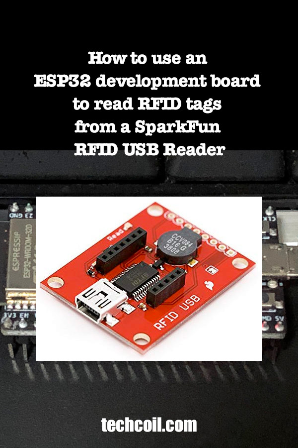
How to use an ESP32 development board to read RFID tags from a SparkFun RFID USB Reader
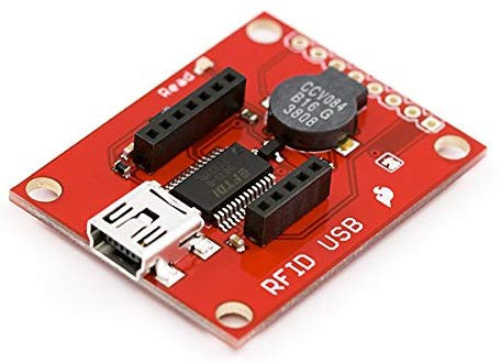
When you have an RFID starter kit from Sparkfun, you will be able to read RFID tags through a serial connection.
Although the SparkFun RFID USB Reader comes with a USB port, you can also read RFID tags with an ESP32 development board.
In case you need it, this is how to use an ESP32 development board to read RFID tags from a SparkFun RFID USB Reader.
Solder GPIO header pins onto the SparkFun RFID USB Reader
First, solder some GPIO header pins onto the SparkFun RFID USB Reader: 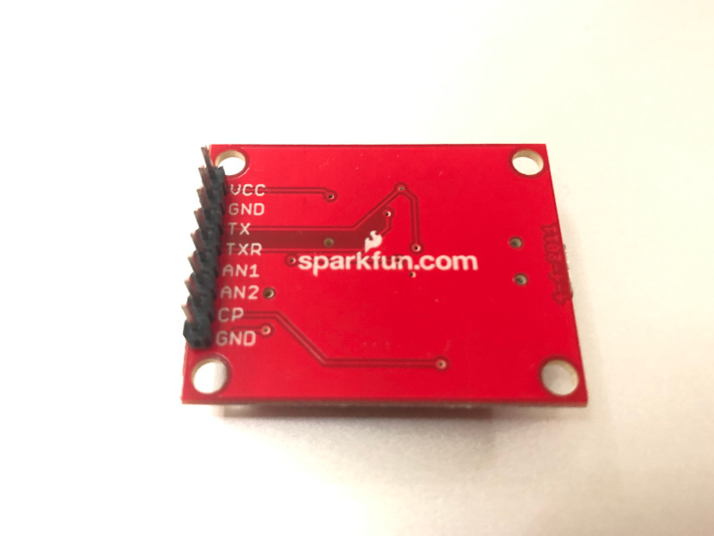
Connecting the SparkFun RFID USB Reader to your ESP32 development board
Once you had soldered the GPIO pins to your SparkFun RFID USB Reader, connect it with your ESP32 development board:
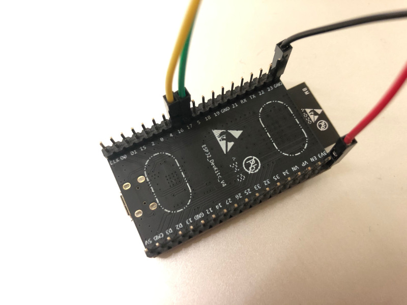
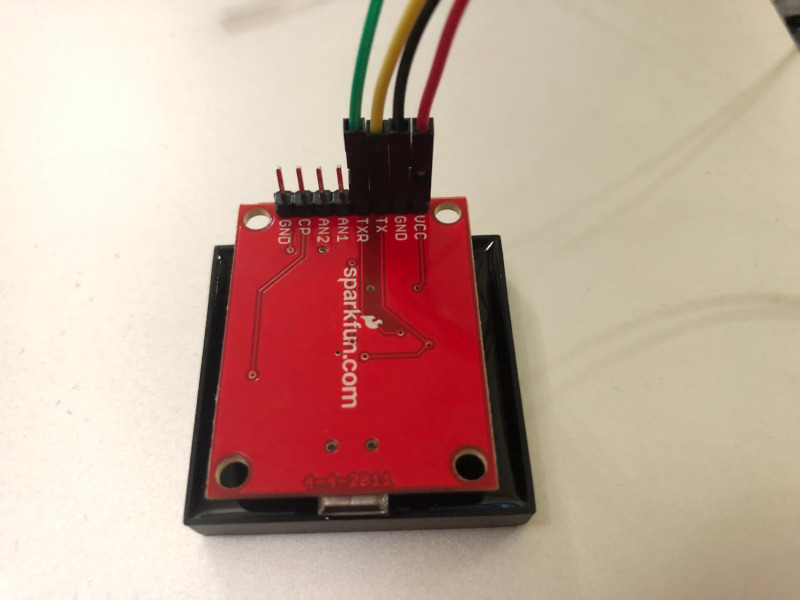
As shown above, I had connected:
- 3v3 pin on ESP32 board to VCC pin on SparkFun RFID reader
- GND pin on ESP32 board to GND pin on SparkFun RFID reader
- GPIO16 pin on ESP32 board to TX pin on SparkFun RFID reader
- GPIO17 pin on ESP32 board to TXR pin on SparkFun RFID reader
Writing an Arduino Sketch to read RFID tags with SparkFun RFID USB reader connected to ESP32 board
After you have connected your ESP32 board to the RFID reader, you can write the software to read RFID tags.
If you enable ESP32 Development on Arduino IDE, then you can upload an Arduino Sketch to your ESP32 board to read RFID tags.
Installing the Arduino libraries to read from the SparkFun RFID USB reader
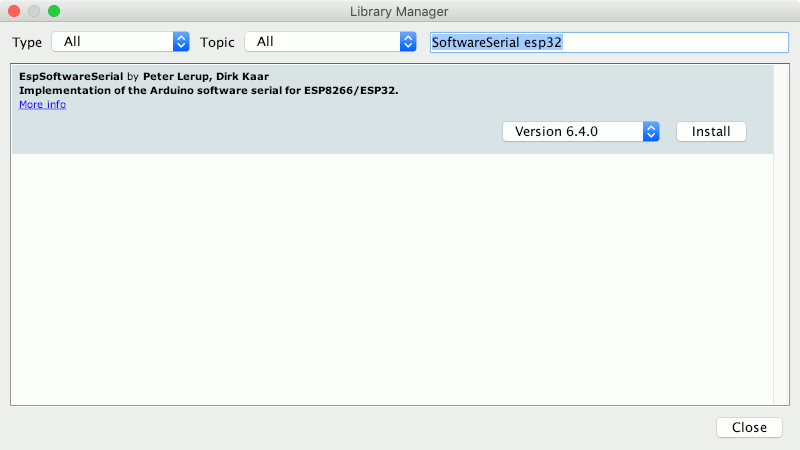
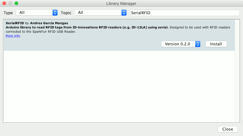
First, let's install the Arduino libraries to help us read from the SparkFun RFID USB reader.
In order to do so, go to Tools -> Manage Libraries.... After you had done so, the Library Manager window will appear. First search for SoftwareSerial esp32 and install the EspSoftwareSerial library:
Next, search for SerialRFID and install the SerialRFID library:
Arduino sketch to read RFID tags with ESP32 board and SparkFun RFID USB reader
After you have installed the Arduino libraries, you can upload an Arduino sketch to read the RFID tags.
Given that, let us look at an adaptation of the example code provided by SerialRFID's author:
#include <SoftwareSerial.h>
#include <SerialRFID.h>

const byte RX_PIN = 16;
const byte TX_PIN = 17;

SoftwareSerial sSerial(RX_PIN, TX_PIN);
SerialRFID rfid(sSerial);

char tag[SIZE_TAG_ID];
char matchTag[SIZE_TAG_ID] = "041A4A48E9F5";

void setup()
{
  Serial.begin(9600);
  sSerial.begin(9600);

  Serial.println(">> Starting SerialRFID example program");
}

void loop()
{
  if (rfid.readTag(tag, sizeof(tag)))
  {
    Serial.print("Tag: ");
    Serial.print(tag);

    if (SerialRFID::isEqualTag(tag, matchTag))
    {
      Serial.println(" / Match: OK");
    }
    else
    {
      Serial.println(" / Match: No");
    }
  }
}
So what is the above code doing?
First, we include the SoftwareSerial and SerialRFID libraries into the sketch.
After that, we initialized an instance of SoftwareSerial and SerialRFID to help us read the RFID tags.
What is the code doing inside the setup function
Next, in the setup function, we set a baud rate of 9600 for two serial ports that we are using. After that, we send an indication to the board's serial port that the setup function had been ran.
What is the code doing inside the loop function
Once we had setup the facilities to read RFID tags, we can attempt to read the RFID tags. Whenever the loop function is called, we call rfid.readTag to attempt to read an RFID tag presented to the reader. If there is one, we then print out the tag id.
After that, we try to match the tag id with a hard coded value. If the tag id matches the tag id from matchTag, then we output " / Match: OK" to the board's serial. However, if both the tag ids do not match, we output " / Match: No" to the board's serial.
Sample output of the sketch
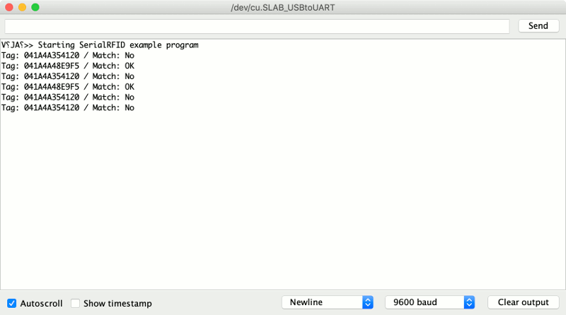
When I run the sketch on my ESP32 development board, I got the following output:
